This is an active window with an embedded KEEL Engine.
Move your mouse over the window and see it update.
Click on the pushbutton to enable the KEEL Engine and try again.
This demonstration is intended to demonstrate a common situation that exists in most control systems. These situations exist in human decision-making and in device based control systems. This demonstration uses a KEEL engine to react to an input signal and generate several analog and binary responses.
In information based systems, this concept can be used to define the importance of information. This could be used to escalate management priorities or redirect resources.
In control oriented systems, the response could be a feedback signal to control speed, current or any other dynamic control variable.
This demonstration of a KEEL based solution also gives some indication of performance. Because this is shown in a graphical way no hard performance figures are calculated. Any real performance numbers would be dependent on the design of the complete system and on the hardware on which the KEEL solution was running.
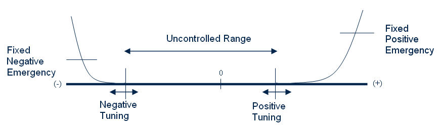
The concept being demonstrated suggests that an input signal has a "normal" range where no feedback or external control needs to be generated. In a medical area this might be a sensed body function that is "normal"; not too high and not too low. In other areas it might be where the system is "balanced". Then there is the case where the input value is out of balance or abnormal. The input signal could be above normal or below normal. In this case, the amount that the input signal is above the acceptable range is used to define a positive output response. A curve defines the magnitude of the response. Similarly, the amount that the input signal is below the acceptable range is used to define a negative output response. A different curve defines the magnitude of the response.
Two input setup signals are provided to adjust the lower and upper "normal" points.
The system also demonstrates the triggering of events when either the positive or negative response signals reach certain values. This might be used to trigger emergency alarms or just to trigger other actions. The analog response signals could be used directly for control or could be used to drive other decisions or escalate the importance of other pieces of information in a complete system.
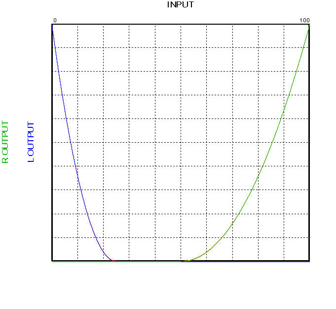
The following graphic shows the function being demonstrated:
This is a very simple application of KEEL technology and is intended only to demonstrate the feedback concepts of this type of a control system.
The user interface code to position the scroll bars and the response indicators would be developed by the programmer. The remainder of the code (Shown graphically below) is created by the KEEL toolkit. It is in the KEEL toolkit, where the relationships between the input signal and the output signals and threshold events are defined. The KEEL toolkit has a menu option to auto-generate the code in many programming languages, such as C, C++, Microsoft C++ .NET, Microsoft C#, Java, JavaScript Python, Microsoft Visual Basic version 6, Microsoft Visual Basic .NET, and PLC Structured Text code, and others. The resulting solution is a very small footprint engine.
This system is based on Compsim's patented and patent pending KEEL technology that covers the toolkit user interface, Compsim's decision-making algorithms, and the resulting KEEL engine.
The snapshot image below shows the complete design of the system from within the KEEL toolkit.
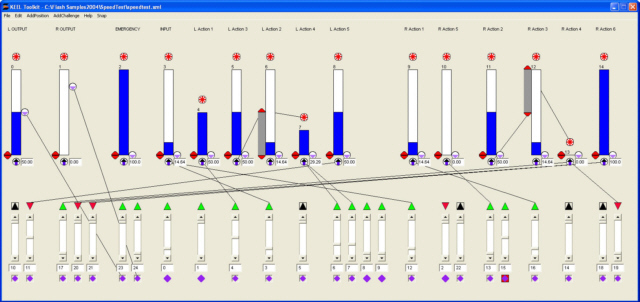
In the KEEL toolkit, the 15 vertical bars indicate decisions or actions. The respective height of these bars indicates their importance. (The 14th bar have 0 height indicating it has no contribution to the system at this time.) The wires between them define how one piece of information impacts another. The scroll bars at the bottom indicate inputs (from outside the KEEL engine or internal connections driven by actions internal to the KEEL engine).
While in the design mode, the designer can visualize how one action can impact another. By adjusting the scroll bars at the bottom of the display, the designer can see the exact system response.
While this image is probably not readable in this document, it is easy to create in the KEEL toolkit. While in the design mode the user can "see" the design in action and graph the activity.
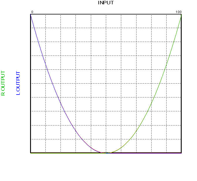
This first graph shows the curves with the left and right scroll bars set to 0.
This second graph shows the result of adjusting the left scroll bar to 50 percent.
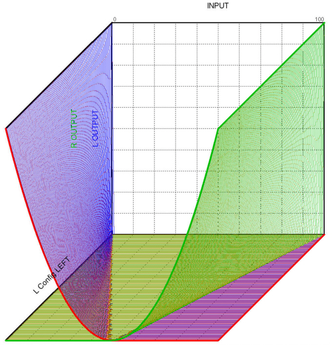
This third graph shows the result of adjustments of both left and right scroll bars throughout their ranges.
This demonstration operates in two modes:
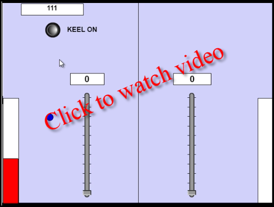
The first mode of operation is shown without executing the KEEL Engine. In this case as the user moves the mouse over the window, a vertical bar rises from the base of the window toward the top depending on how far from left to right the mouse is in the window. A text box shows the 'x' position of the mouse as it moves across the window.
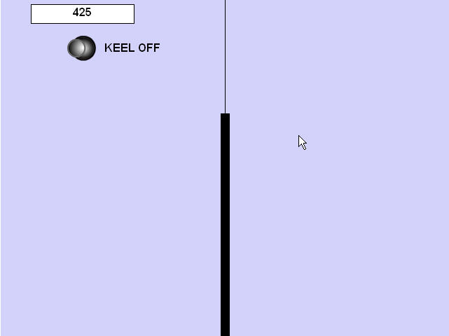
A push button is provided to switch to the second mode. This hides the initial vertical bar and loads a number of other screen items:
To generate rapid changes to a simulated input signal, this demonstration uses the position of the mouse. As the user waves the mouse cursor over the window, the KEEL engine will determine whether an output response is necessary and if so, how much of a response.
The vertical scroll bars allow the user to adjust when to begin applying a positive or negative response signal. The farther away from the center of the window, the larger the response signal.
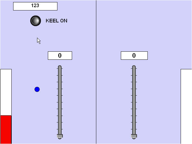
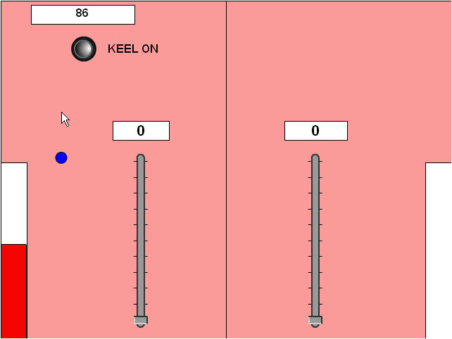
When the response signal (positive or negative) reaches predefined magnitudes (they are different - 50 on the left and 80 on the right), the screen background will turn red indicating that these thresholds have been reached (an emergency situation). In a real application these "events" could trigger any type of response.
This screen shot shows the mouse in a position that controls the ball slightly below the vertical midpoint (the emergency threshold) and the screen color is blue.
This screen shot shows a slight repositioning of the mouse where the blue ball rises above the threshold, which, in turn, changes the screen color to red.
The demonstration applications on Compsim's web site are not intended to be tutorials on the use of the KEEL toolkit. If you are interested in learning more about Knowledge Enhanced Electronic Logic and KEEL technology, please contact Compsim at the phone number listed below.
|
Copyright , Compsim LLC, All rights reserved |